| Date: | March 16/17 |
| Lecture: | 25 |
| Code: | TBD |
| Status: | Complete |
| Lesson Slides | ECE_383_Lec25.pptx |
Filtering
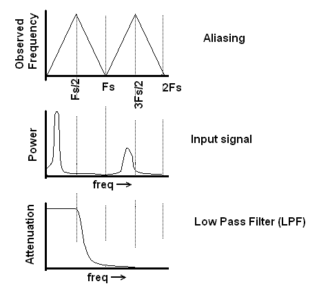
Whenever you sample an analog signal at discrete times, you are going to run into aliasing problems with frequency folding. This creates problems in sampled systems like an ADC because noise anywhere in the spectrum will fold back into our sampling region as shown in the figure below.
In order to address this problem we will utilize a principle called attenuation. Attenuation is the process of changing the amplitude of a waveform without changing its frequency. The amount of attenuation is quantified in terms of decibels.
dB = 20 * log (V_out/V_in)
| V_out/Vin | dB |
| 1 | |
| 1/10 | |
| 1/100 | |
| 1/1000 | |
| 1/256 | |
| 1/1024 | |
| -3dB | |
| -68dB |
Question If you input a 1v sin wave into a circuit that attenuated it by -68dB, what would the amplitude of the output waveform be?
Question If you reduced a signal by a factor of 1/256, how many dB would you need to attenuate it by?
Low Pass Filter
We will use a circuit called a low pass filter to attenuate signals. It has some nice properties which make it well suited to this task. You can build an analog low pass filter by putting a resistor and capacitor in parallel. Our ATLYS boards have this circuit arrangement as shown by the pairs (R153, C43) and (R154,C44) in the schematic below.
Strategic parameters for this first order filter include...
- Corner frequency: 1/6.28*R153*C43 = 2854hz
- Roll off: -20dB/decade
Before moving on, its important to really understand the slope of the roll-off, -20dB/decade. A decade is a factor of 10, 2 decades is a factor of 100. If you increase a 10kHz waveform by 1 decade then you would have a 100kHz waveform. If you increases a 2kHz waveform by 2 decades then you would have a 200kHz waveform. If you increased a 2KHz waveform by 2.5 decades you would increase it frequency by a factor of 10^2.5 = 316, resulting in a 632KHz waveform.
Filter Design Problem
Lets test out understanding of all these concepts with a filter design problem.- Aliasing:
Your sampling an analog signal at 48kHz. List all the frequencies that will look like 2kHz signals.
- Decades:
A first-order LPF has a cutoff frequency of 2kHz. Describe the attenuation of a 80kHz input signal in decibels and as a ratio of output voltage to input voltage.
- ADC convert:
You are working with a 10-bit ADC and would like to attenuate some frequency below 1/2 ULP. How many dB will be required to achieve this?
- Sampling frequency:
Given:- Signal of interest is 0-2KHz
- 2nd order filter
- 10-bit ADC
-
Sampling frequency:
- Signal of interest is 0-2KHz
- 1st order filter
- 8-bit ADC
- Sampling frequency:
Given:- Signal of interest is 0-2KHz
- 1st order filter
- 10-bit ADC
- Filter specs:
Given:- Signal of interest is 0-2KHz
- 8-bit ADC
- Maximum possible sampling rate of 80KHz
- Signal bandwidth:
Given:- 16-bit ADC
- 4th order filter
- Sampling frequency 250kHz